
Resources for SEEN Safety System installers
Installing a SEEN IRIS 860 sensor or an IRIS-i camera?
Download the SEEN System Installation Guide for your reference during the installation process.
Refer to the relevant Machine Template, which shows the sensor’s placement and mounting options specific to the machine you're installing it on. Ask the on-site manager for the template or download below.
Watch our Installation videos (below) for a quick how to guide to an easy installation.
Refer to the Installation Checklists to check and test that the installation is complete and correct.
Essential Resources


Installation Videos
1. How to install an IRIS 860 sensor
2. How to install an IRIS-i camera
Test your installation
Check the sensor angle
The face of the sensor should be angled slightly downwards so that the figure on the alignment sticker is upright.
Check the power supply
Switch the vehicle on. The sensor LED should be a steady green.
Test functionality
When detecting the sensor will emit a loud audible alert tone and the LED will be red.
Place a reflective safety vest (or other reflective item) in the sensor’s detection zone (approximately 2-3 meters from the sensor). The sensor should not alert.
Now, put the vehicle in reverse gear and repeat the test. This time the sensor should alert.
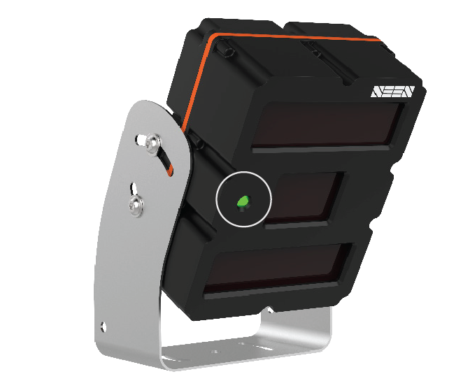
The sensor LED should be green whenever the vehicle is switched on.
Trouble shooting
1. The sensor LED is green, but the sensor will not alert.
Possible cause: The reverse signal is not connected. By default the sensor is set so it can only alert while receiving a direction signal (usually reverse) from the machine.
Solution: Ensure that all 3 wires on the sensor (or Cab Box) power cable are correctly wired to the machine’s reverse signal, power, and ground.
Possible cause: The retroreflective material is too close to the sensor.
Solution: Move further back. Detection starts 0.8m /2.6ft from the sensor face.
Possible cause: The retroreflective material is worn out or is of insufficient size to enable detection.
2. A sensor that is pre-set to only alert during reverse, will alert when the vehicle is not in reverse.
Possible cause: The reverse signal input wire is twisted together with the ignition power wire, meaning the reverse signal is always high.
Solution: Ensure that the 3 wires on the sensor (or Cab Box) power cable are correctly wired to the machine’s reverse signal, power, and ground.
3. The sensor and/or Cab Box are correctly wired but the sensor/s do not behave in the expected way.
Possible cause: Electrical earthing issue on the reverse signal.
Solution: Check that the ground reference on the reverse signal is the same as the ground reference on the sensor power supply. Refer to full Installation Guide for more information.
4. The Cab Box is correctly wired but the sensor/s do not behave in the expected way.
Possible cause: The Cab Box is wired to the machine using the 5-PIN sensor power cable, instead of the 4-PIN cab box power cable supplied with the cab box.
Solution: Use the 4 PIN Cab Box power cable supplied with the Cab Box. Do not use the 5 PIN sensor power cable supplied with each sensor.
5. The sensor repeatedly beeps and flashes with the sequence long-short-short, long-short-short.
Cause: Blocked window.
Solution: Clean the windows and the self-check alert should cease. If the sensor is operating in a cold-store freezer, ice on the window maybe triggering the self checking function. Refer to the Internal Self Check section in the Installation Guide.
6. The sensor is beeping and flashing and the sequence is NOT long-short-short, long-short-short.
Cause: Internal fault detected.
Solution: There are no user serviceable parts. Contact your supplier for repair or replacement.
7. At start-up the sensor gives a continuous tone alert when the vehicle is in gear.
Cause: Test Mode may be enabled and has been inadvertently activated. Refer to the full Installation Guide for more information.
IRIS 860 settings
The IRIS 860 sensor is preset with factory default settings which include the detection zone, direction based signalling and alert volume. It is the onsite Manager’s responsibility to make decisions about the sensor settings that best suit the specific work environment, and to change the settings if required, using SEEN’s setup app.
If you have been instructed to change the settings, you will need to liaise with the onsite Manager, and refer to the How to change the sensor settings guide.